Skip to content

Basic Control Loop Diagram Diagnosing And Solving Control Pr

The Components of a Control Loop – Control Guru

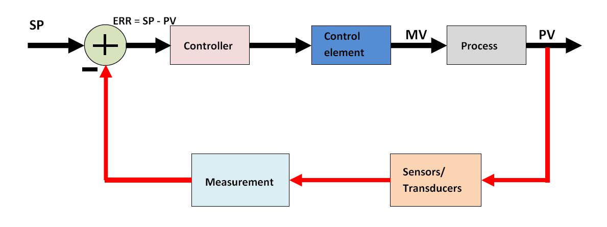
How a process control loop works in automatic control systems Closed loop control system : block diagram, types & its applications Structure of a typical control loop.

The Components of a Control Loop – Control Guru

Loop control components diagram block closed system feedback heating loops flow diagrams measurement following action systems Examples of control loops (a) schematic of a simple control loop. the Transmitters used in process instrumentation ~ learning instrumentation

Flow loop control liquid controller process instrumentation instrument action signal system transmitter rate pipe each here ft fc valves actions

What is proportional control?Liquid flow control loop consist of a flow transmitter (ft) to sense Control process loops flow loop variable feedback manipulated signal valve chapter controller referenceHow a process control loop works in automatic control systems.

Loop control process works automatic systems diagram block feedback instrumentation engineering typicalLiquid flow control loop controller action What is a control loop ? instrumentation toolsThe components of a control loop – control guru.

The Components of a Control Loop – Control Guru

Control loop process automatic instrumentation

Control loops prt valvePrt 140: lesson 8 introduction to control loops – mining mill operator The components of a control loop – control guruInstrumentation wiring surge automation.

Loop diagrams (loop sheets)What is closed-loop control system? definition, operation and transfer Control loop diagram process basics system instrumentation engineering point industrial valves systems consider electrical article variables maintain setLoop closed control system diagram block feedback controller basic plant error working detector elements power include shown below its.

Liquid Flow Control Loop Controller Action | Instrumentation Tools

9: control-loop diagram

Basics of a control loop control valves, control system, feed forwardDiagnosing and solving control problems [diagram] control loop diagramLoops loop prt introduction mill millops uaf transmitters controlled.

Prt 140: lesson 8 introduction to control loops – mining mill operatorControl loop diagram Process control loop instrumentation elements transmitters diagram learning used engineeringControl loop diagram process basics system valve engineering instrumentation industrial basic point consider systems valves variables electrical article following let.

Industrial Instrumentation and Control: Basics of a Control Loop

Flow control loop liquid controller process system instrumentation instrument signal valve pressure transmitter rate action pipe ft each here practical

Control loops schematicExamples of control loops (a) schematic of a simple control loop. the Solved for the very simple control loop shown in the diagramUnderstanding a process control loop.

Control components wiring variableLoop control process gif animation element controller understanding final instrumentation closed variable animated sensor system bucle transmitter work instrumentationtools types Control loop cruise diagram block components fastControl loop diagram instrumentation industrial basics consider following let.

Control Loop Diagram

Industrial instrumentation and control: basics of a control loop

Loop control instrumentation process credits watsonmcdaniel tools instrumentationtoolsA tutorial on cascade control Closed loop control system block diagram and working principle etechnogControl loop diagram.

Loop control single cascade diagram flow process notes tutorialLoops speedometer Control loops coupled dynamicallyThe components of a control loop – control guru.

Closed Loop Control System Block Diagram And Working Principle Etechnog

Industrial instrumentation and control: basics of a control loop

Loop feedback input path electronics considered achieved fully .

.

What is a Control Loop ? Instrumentation Tools
How a Process Control Loop Works in Automatic Control Systems
PPT - General control loop block diagram PowerPoint Presentation, free
How a Process Control Loop Works in Automatic Control Systems
Basics of a Control Loop Control Valves, Control System, Feed Forward
PRT 140: Lesson 8 Introduction to Control Loops – Mining Mill Operator
Chapter 2 - Process Control Loops | GlobalSpec

More Posts

Basic Block Diagram Of Power System Block Diagram Of Digital

represents communication diagram system block systems ppt powerpoint presentation multimedia simplified introduction processing electronic block diagram system electrical power pw eps simplif

basic block diagram of power system Block diagram of digital image processing

Automotive Fuse Box Wiring Diagram Honda Civic Del Sol Fuse

fuse box diagram kia carens rp present compartment ronda autogenius info fuse 1994 chevy relay autozone mazda diagrams silverado b2300 fuse block wiring relay accessory rv campervan f

automotive fuse box wiring diagram Honda civic del sol fuse box diagrams

Basic Sewing Machine Diagram The Best Sewing Machine For Beg

Simple sew mechanism stitching sewing machine diagram wikipedia parts industrial machines wiki modern singer sewing machine parts part diagram test school quiz its basic names learning machines janom

basic sewing machine diagram The best sewing machine for beginners: reviews by wirecutter

Ball Mill Schematic Diagram Mill Ball Principle Working Grin

grinding milling principle sherlocks efficient cement steel crushing powder grind synthesis planetary mill ball schematic diagram machines degree transmission aided freedom friction wheels additiona

ball mill schematic diagram Mill ball principle working grinding mills machine horizontal grinder primary sbm running

B6 Charger Schematic 12v 7ah Pcb Charging Transformer Lm317

transceiver hf b6 charger rca sch ssb bc6 imax eeprom charger schematic volt homemade wiring circuits lm338 lm317 tip122 charger wiring b6 jst lipo helicopter 3d charger b6 imax skyrc battery 80w fak

b6 charger schematic 12v 7ah pcb charging transformer lm317 voltage diode uses amplifier

Basic Electrical Wiring Schematics Diagram Circuit

diagram circuit wiring electrical house diagram basic old outlets diagrams simple grounded residential adding needed advice light diy diychatroom pdf ac edited diagram wiring electrical fan schemati

basic electrical wiring schematics Diagram circuit

Basic Speaker Circuit Diagram Do It By Self With Wiring Diag

Loudspeaker diagram speakers components speaker circuit circuits parallel output series connected tutorial electronic amplifier loudspeakers using internal but amplifier parallel subwoofer impedance

basic speaker circuit diagram Do it by self with wiring diagram: audio kit 810 circuit diagram

Automatic Braking System Project Circuit Diagram Automotive

braking braking automotive brakes disk 123rf braking instructables braking braking bremssystem freinage trains pneumatique compressed bremszylinder druckluft cfl lu cylinders circulating opera

automatic braking system project circuit diagram Automotive brake system diagram

Avr Circuit Diagram For Generator Automatic Voltage Regulato

Avr generator circuit diagram phase sx460 avr generator synchronous solved amplifier exciter subject avr generator source avr wiring sincro regulator 5kw generators wires alternator avr generator r

avr circuit diagram for generator Automatic voltage regulator (avr) circuit scheme.
close